Feed Through Patch Panel Recommendations

Patch panels act as the central role in the administration of the telecommunication network. They form the primary link for collecting cables and routing data to the place where it needs to be. The most copper cables in network presently use Cat5e patch panel or Cat6 patch panel. However, there are various styles of Cat6 patch panels on market, like punch down or feed through patch panels. Consumers may be confused when they need to select one. Here I’d like to talk about Cat6 feed through patch panel and recommend some for your reference.

Why Choose Feed Through Patch Panel

Compared with punch down type, there is no need to punch down cables with feed through panel. Unlike the punch down panel that needs to punch down Ethernet cables for the rear side, feed through patch panel have RJ45 ports on both sides, making install cables is fairly simple. Though the price is a bit higher, the feed through panel saves time and energy for cable management.

Feed Through Patch Panel Recommendations

FS.COM offers feed through patch panels with different styles making them ideal for any installation in server racks. Here is a video to show the products.

Unshielded Feed Through Patch Panel

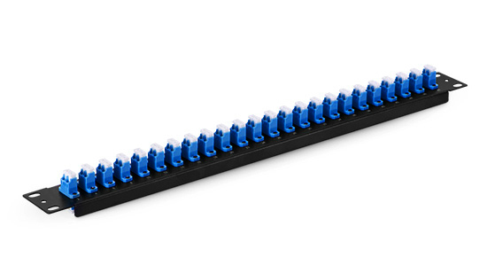
Unshielded patch panel is used to connect unshielded cables that actually with faster transmission in the absence of electromagnetic interference (EMI). The following is a 24 port Cat6 unshielded feed through patch panel at the price of 30 dollars. It meets Cat6 specifications and works with T568A and T568B wiring to comply with industry standards. Made from SPCC+ABS plastics material, the Cat6 patch panel features 24 numbered ports to help you identify connections. And it’s supplied in black color.

unshielded feed through patch panel

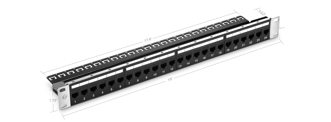
Figure 1: 24 Port Cat6 Unshielded Feed Through Patch Panel

Shielded Feed Through Patch Panel

Shielded patch panels are recommended for high EMI environment, because shielded cables can more effectively block interference. Therefore, shielded panel is more expensive than unshielded one, this 24 port Cat6 shielded patch panel costs 43 dollars at FS.COM. Made to be efficient and durable, the Cat6 feed through patch panel is constructed with a fully enclosed, 6 port module design, which provides flexibility and protection of printed circuitry of termination. With a cable management bar on the rear, it helps Cat6 cables to pass through patch panel in a neat and organized way.

shielded feed through patch panel

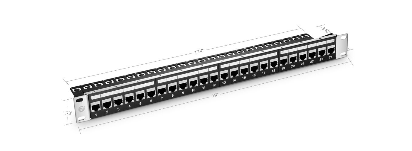
Figure 2: 24 Port Cat6 Shielded Feed Through Patch Panel

Blank Keystone Patch Panel

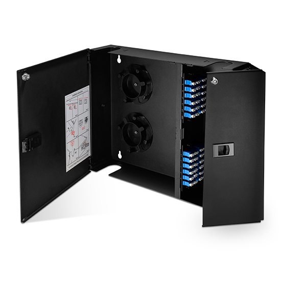
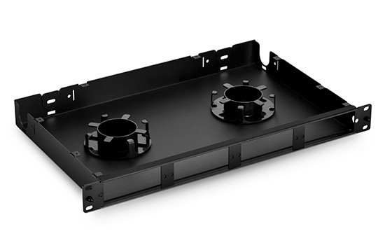
To meet customers’ different usages, FS.COM produced blank keystone patch panels that are available in 24 port and 48 port. Here is the 48 port patch panel which offers unlimited flexibility and ease of installation to the customers. The port openings will accept both Cat5e and Cat6 insert modules, thus a mixed connection will be made. Designed with a stainless steel cable manager on the rear, this patch panel keeps cabling neat and tidy, and can mount to any standard 19 inch server rack. Beside, it has a favorable price of 11 dollars.

blank keystone patch panel

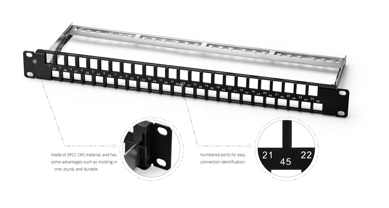
Figure 3: 48 Port Blank Keystone Patch Panel

Conclusion

To sum up, when you need to connect the unshielded cables choose the unshielded feed through patch panel, while use the shielded panel to link shielded cables. And if you want to make a mixed connection, choose the blank keystone design. FS.COM patch panel offering includes copper and fiber types which are in stock and ship the same over the world. Welcome to pick at FS.COM!

Understanding the Two Terms: EVPN vs VXLAN

EVPN vs VXLAN is one of the most popular network technology. They were developed because enterprises need to deliver data and share resources at different geographical locations. Therefore, the efficient, reliable and high speed interconnection is required for the different sites. EVPN vs VXLAN are born as the new upcoming technology to meet today’s network demands.

Introduction of EVPN vs VXLAN

What Is EVPN

EVPN or Ethernet VPN, is regarded as a next generation all-in-one VPN technology. It offers Ethernet multipoint services over MPLS (multiple protocol label switching) or IP networks. Using EVPN service and with the help of MPLS core network, users can connect the offices located in different areas via the lay 2 network for sending messages. This is similar to the work that extends LAN to WAN. Also, it greatly reduces the difficulty of network deployment and maintenance. In addition, EVPN supports MPLS, VXLAN, and other data plane encapsulations.

EVPN

Figure 1: Example of EVPN

What Is VXLAN

VXLAN is short for Virtual Extensible LAN. As the name implies, we know this technology is designed to provide the same transmission service for Ethernet connection that VLAN do today, but in a more extensible way. Technologically, VXLAN is a MAC in IP/UDP encapsulation technique with a 24 bit segment identifier in the form of a VXLAN ID, which is larger than the LAN with 12 bit segment ID. Also, it supplies a way to span Layer 3 network by VXLAN tunnel that is established between VETP (VXLAN Tunnel End Point). Thus it has a higher scalability to address more Layer segments.

vxlan

Figure 2: Example of VXLAN

Route VXLAN with EVPN

EVPN vs VXLAN are both virtual technology. VXLAN explained that EVPN could be the control plane of VXLAN, which uses the BGP (Border Gateway Protocol) to provide high scale, multi-tenant separation and fast convergence for host and VM mobility. So EVPN helps us to deploy VXLAN tunnels without controllers. Routing VXLAN is available in two architectures—centralized or distributed. Compare these two approaches, it’s clear that the distributed architecture will simplify the traffic flow. And here is the place for routing VXLAN with EVPN according to VXLAN tutorial.

For the distributed architecture, asymmetric IRB (integrated routing and bridging) and symmetric IRB are the two models to achieve inter-subnet routing with EVPN. Both of them are valuable, so choose the suitable model for your legacy network system.

FS.COM Solution for EVPN vs VXLAN

FS.COM S5850 series switches are designed for hardware based VXLAN function. The following is a 10gb Ethernet switch from FS.COM.

This S5850-48S6Q is a Layer 3 switch. This fiber switch has an advanced architectural design with 48 port 10G SFP+ and 6 port 40G QSFP+ in a compact 1U form factor. It can provide extensive data center service features and switching capacity of 1.44Tbps. Besides, the wind direction of the switch is front-to-back, or you can change it to back-to-front. With support for advanced features, including MLAG, VXLAN, IPv4/IPv6, SFLOW and so on, this switch can help enterprises to build a scalable data center network platform in the cloud computing era.

switch

Figure 3: S5850-48S6Q Switch

Conclusion

From the above, we have a better understanding of EVPN vs VXLAN. FS.COM, as an excellent provider of enterprises solutions, offers different kinds of switch such as PoE network switch, SDN switch to satisfy customers’ various network demand.

Things You Should Know about IP SAN vs FC SAN

Now, data has become the most valuable asset since the Internet and e-commerce are growing at an explosive rate. How to store, protect and manage vital data in an effective way is a big challenge for IT technicians. Here, SAN, storage area network, has been developed to provide a creative model for data storing in the data center. Within its development, two types of IP SAN vs FC SAN has gained enough discussion. Today, we’ll talk about IP SAN vs FC SAN.

SAN

Figure 1: SAN Diagrammatic Drawing

What Is IP SAN

From IP SAN wiki, we know it means internet protocol storage area network. It’s a SAN that uses iSCSI protocol, a transmission standard over TCP/IP, to transfer block data over an Ethernet network. IP SAN allows different servers to access pools of the shared block storage devices by storage protocols. Besides, IP storage network can be extended to Wide Area Network via IP router or Gigabit Ethernet switch, which is good for synchronous applications like remote disk copy.

Advantages:

In addition, IP SAN brings several advantages.

  • Low cost. Ethernet, switches and IP network exist almost everywhere. There’s no need to buy extra equipment for connectivity. You can use the existing network to build a SAN.

  • Easy access. The IP technology makes it easier to achieve remote storage. Also, there’s no distance limitation over LAN/WAN connectivity.

  • Competitive speed. Thanks to the advent of 10G Ethernet and 10gbe switch, the transmission bandwidth has been increased. This leads to an improvement of the overall performance.

What Is FC SAN

FC SAN is a fiber channel network in which the SCSI-FCP protocol runs. Based on fiber channel technology, technicians use fiber switch to connect the storage devices and the servers, so as to build a regional network dedicated to data storage. Within FC SAN, the data will be transferred directly at an extremely high speed.

Advantages:

As an open, high-speed serial interface, FC SAN has some advantages.

  • High transmission bandwidth. Due to the design of fiber channel, it can deliver data at 1Gb/s, 2Gb/s, 4Gb/s, 8Gb/s and more. Also, the fiber channel can provide excellent redundancy.

  • Flexibility and extensibility. FC SAN has overcome the traditional cable limits that are associated with SCSI. Thus it greatly expands the distance between servers and storage devices, in order to increase the possibility of more connections,

  • Wide application. As the technology matures, FC SAN is widely used in big IT User Base.

IP SAN VS FC SAN

Figure 2: IP SAN and FC SAN

IP SAN vs FC SAN: What Is the Difference?

Here is a table shows the differences of IP SAN vs FC SAN.

IP SAN
 FC SAN
 Network  Gigabit Ethernet network  fiber channel network
 Cost  Low  High
 Transmission speed  Fast  Extremely fast
 Transmission protocol  fiber channel TCP/IP
 Extensibility  More easier to extend  Easy to extend

IP SAN vs FC SAN, IP SAN is generally regarded as the lower cost, simpler to manage than the FC SAN. FC SAN needs special hardware like fiber switches or host bus adapters, while the IP SAN just requires the existing Ethernet networking hardware. Therefore, FC SAN is the ideal storage platform for many business-critical applications. And IP SAN is the suitable choice for those organizations that want a cost-efficient solution.

Conclusion

IP SAN vs FC SAN, it’s important to know their advantages and differences when you decide to build a SAN. Make a suitable choice based on your unique demands and knowledge. Any questions about SAN setup on switches, contact us via sales@fs.com.


What Is VLAN Switch and Why Do We Need It?

VLAN or virtual LAN is a type of LAN that is defined to map workstations based on everything except for geographic location. It develops when the network has increased in size and complexity, and many companies require more access ports or a network design. Basically, it’s a networking technology which allows the network to be segmented logically without geographic restrictions. But how much do you know about VLAN switch?

What Is VLAN Switch?

VLAN switch is built on the fiber optic switch of LAN, which realizes the division and management of logical working group as a software. As defined in IEEE standard 802.1Q, VLAN switch can provide a way to transform one network into multiple broadcast domains. And each broadcast domain is usually matched with IP subnet boundaries, so that each subnet has its own VLAN. Therefore, users can obtain various wired LANs for different purposes that are co-existed physically, which means you don’t need to buy additional hardware or cabling at a large expense. With the development of IoT, VLAN switch is extremely useful.

VLAN switch

Figure1: VLAN Example

Why Do We Need VLAN Switch?

As an important feature of modern network technology, VLAN switch not only can create a separate broadcast domain, but also isolate traffic. Besides, it enjoys several advantages as followed that help to optimize the network.

  • Security. Separating system of the VLAN switch can isolate the sensitive data from the general network, so that people will have slim chance to see the information that they aren’t authorized to see.

  • Performance. With LAN data rates increase, traditional routers may generate a bottleneck when sending data in software. VLAN switch can settle this issue. It can segment LAN into VLANs to achieve multiple broadcast domains, which helps to reduce unnecessary network traffic and increase the bandwidth. After a successful setup, VLAN switch will benefit the whole network performance.

Where to Buy VLAN Switch

Using network switches to realize VLAN switch is today’s common solution for network congestion. FS.COM develops a series of network switches such as 1G switch, 10GbE switch, 40G switch and 100G switch. Some products offer VLAN such as S3800-24T4S 24-port 10/100/1000 base-T Gigabit stackable managed switch and 24-port Gigabit PoE+ managed switch, while some are without the support of VLAN like S5800-48F4S 48-port Gigabit SFP L2/L3/MPLS switch and N8000-32Q (32*40GbE) 40GbE spine/core layer switch. Now, we’ll take 24-port Gigabit PoE+ managed switch as an example.

This S1600-24T4F PoE network switch supports 24 RJ45 ports with each PoE power consumption at 30W. For safety, each port is equipped with separated overload and short-circuit protection, and along with LED to show power status. When connected with CAT5e, each port can achieve single port power and data transmission. It accepts the dual-mode PoE standard and compliant with IEEE802.3af/at. Besides, its switching capacity can reach 52Gbps. The switch helps secure the network through supporting dynamic or static binding by users’ definition like IP, MAC, VLAN and so on.

Figure2: 24-Port Gigabit PoE+ Managed Switch

Summary

VLAN switch is a wonderful technology and tool to assist your network. Using FS.COM VLAN switches just by logging into the switch and entering the parameters for the VLAN, you can easily create a VLAN and enjoy your perfect networking experience.


Patch Panel Cable Management

Patch panel cable management is a common practice in network system. This because technology develops at an unbelievable speed, consequently, today’s server rooms are featured with a large number of different bandwidth-intensive devices, such as clustered storage systems, blade servers, virtualization applications or some other backup devices. These devices are all interconnected via network cables or cable management tools. Besides, it’s known that challenges in server rooms arise not only with trying to pursue the increasing demand of higher performance and flexibility in order to achieve a scalable and manageable cabling infrastructure, but also with evolving cabling industry standards, which sometimes may determine future’s cabling offerings standards for technological growth. To solve those problems, patch panel cable management is a wise choice in the physical plant.

Benefits of Patch Panel Cable Management

Patch panel cable management describes how fiber cables are connected and managed in a patch panel. Fiber optic patch panel is a very popular cable management tool used for wiring fiber cables in an organized way. And a correct patch panel cable management will deliver several advantages, which will enhance one’s network availability.

  • Reduced signal interference. Patch panel makes the cables in their corresponding positions, that means the cables will not interfere with each other. This can greatly reduce the crosstalk and interference between cables and ensure cables’ performance.

  • Improved serviceability. Patch panel allows technicians to recognize which cable should be changed or upgraded easily, minimizing working time and improving safety.

  • Cooler function. Thanks to the fix positions of cables in a patch panel, there is more space within a rack for air flowing. It brings down the whole equipment running temperature.

  • A roadmap for growth. Labels on the patch panel is an effective cable management which gives the direction to technicians to scale and adapt to changes in cabling infrastructure as well as reducing service time.

Tips for Patch Panel Cable Management

Here are several patch panel cable management tips for network installers.

Start with measuring. Remember the adage “Measure twice, cut once”. Measure the cables’ length needed for a patch panel carefully, to avoid messy cabling and expensive cable waste.

Don’t forget the labels. Just take some time to mark clearly on the connection point, which will pay off in the long run.

End with testing. After connecting cables via patch panel, test each cable by using a quality tester. If the test doesn’t pass 100%, reconfigure the cable. Believe me, this step will avoid lots of extra work in the end.

Patch Panel Cable Management Solutions

Patch panels are available in different categories based on various ports and designs. Confused about which one will work for your application? FS.COM is the right way for your cabling design. The following are the two products sold well from FS.COM.

24 port fiber patch panel is the best choice for small LAN cable management. This 24 port LC duplex fiber patch panel with a max cable capacity of 48 OS2 single mode fibers is suitable for 1U high 19 inch frame rack mount or cabinet. The ports are in the upright design with folded sides, providing a cold aisle orientation for cables.

24 port patch panel

Wall mount patch panel is a wise practice in the limited room. This fiber optic wall mount patch panel can hold 4 standard FHD series adapter panels. The max cables capacity of this type is 96 fibers. Equipped with slack spools, strain relief and silica gel stopple, the wall mount patch panel can protect cables bend radius and prevent dust.

wall mount patch panel cable management

FS.COM patch panel cable management tools are ideally designed to store, protect and terminate fiber cables and connectors. Need help with setting up a patch panel cable management? FS.COM is the definitive choice for all your optical fiber needs.


1U Rack Mount Enclosure Inside Cabling Installation

Rack cabling may be the backbone of one’s information technology operation. All data or signal are delivered by the cables, so maintaining and running the critical circuits that are managed by these cables are of great importance. Any mishandled cables on the key link paths can lead to bad results, such as data transmission errors or performance issues. So how to organize and protect fiber cables? This 1U rack mount enclosure will help you. First, let’s look at the structure of 1U rack mount enclosure.

Structure of 1U Rack Mount Enclosure

Before we properly use fiber optic patch panel, we should have a better understanding of its structure. The following 1U rack mount patch panel is from FS.COM. It can support 4 fiber adapter panels or MTP/MPO fiber optic cassette. The top cover can be removed, which is convenient when installing the adapter or cassette. Inside the enclosure, there is nothing except two fixed screw holes position, which enables users to settle the panels or cassettes. Each rack mount enclosure is shipped with an accessory pack that includes mounting screws, spools, bend radius brackets for proper installation and cable ties for cable management.

1U Rack Mount Enclosure

Devices Used for 1U Rack Mount Enclosure Inside Cabling

There is a video to show clearly how 1U rack mount fiber enclosure inside cabling works. Here, we need 24 fiber optical splice tray, LC fiber adapter panel and spliced fiber pigtail.

Splice tray is a device used with other equipment to hold and protect optical fibers. This 24 fiber optical splice tray is equipped with self-contained slacking and spooling, mechanical splice holder, self-stacking modules with side latches and clear plastic hinged cover, designed to safely route and store optical fiber.

LC fiber adapter panel is designed for use with FHD series rack mount enclosures, providing a good protection for cables.

Fiber pigtails are used in terminating fiber cables through fusion splicing, in order to achieve accurate mounting for precision alignment of fiber optical components.

1U Rack Mount Enclosure Inside Cabling Installation

According to the video, the installation can be divided into two parts, fiber optic splice tray installation and cassette or adapter installation.

Step one, install fiber optic splice tray first. Undoing the screw to remove the top cover. Put 24 fiber optical splice tray into the 1U rack mount enclosure, and align the screws at the screw holes, then use a screw to fix it. Position another splice tray upright the fixed one. The 1U enclosure can hold 4 splice trays. Last, use a cable tie to make sure the fiber cords at the right location.

Step two, install cassette or adapter. Place slack spools over plastic rivets studs on sliding tray in a new 1U enclosure, and use screw to fix slack spools. Then insert LC fiber adapter panels into the enclosure. Unplug dust caps and connect the fiber pigtails. Note that make the pigtails go through the grommet for dust prevention. Finally, close the top cover.

FS.COM developed the 1U rack mount enclosure inside cabling installation to guarantee the smooth operation and efficient cable management of customers’ network. More details, please visit FS.COM.


Why Third-party 40G QSFP+ Transceiver, Instead of OEM QSFP Module?

For the data center or network upgrade, 40G network is a trending choice. Then where do you buy the 40G QSFP transceiver? Will you choose an OEM one or a third-party one? There are some differences between third-party 40G QSFP transceiver and OEM 40G QSFP transceiver, which will be shown below.

third-party 40G optical transceiver Vs OEM 40G QSFP

Features of OEM 40G QSFP Transceiver Modules

As we know, the OEM 40G QSFP transceiver from name brand like Cisco, Juniper and Brocade is widely used in data center and enterprise network. They all have some great features. The Cisco 40G QSFP transceiver offers a wide variety of high-density and low-power 40 Gigabit Ethernet connectivity options for data center, high-performance computing networks, enterprise core and distribution layers, and service provider applications. Here are some benefits of Cisco 40 Gbps transceiver:

  • Hot-swappable input/output device that plugs into a 40 Gigabit Ethernet Cisco QSFP port
  • Flexibility of interface choice (for different reach requirements and fiber types)
  • Interoperable with other IEEE-compliant 40GBASE interfaces where applicable
  • Certified and tested on Cisco QSFP 40G ports for superior performance, quality, and reliability
  • High-speed electrical interface compliant to IEEE 802.3ba
  • QSFP Form factor, 2-wire I2C communication interface and other low-speed electrical interface compliant to SFF 8436 and QSFP

40G QSFP

The Brocade 40 Gbps transceiver supports highly reliable operations in data center and is optimized for Brocade switching platforms. It undergoes strict qualification and certification testing.

Why Choose 3rd 40G QSFP Optical Transceivers Over OEM?

40G QSFP transceiver from Cisco and Brocade is reliable and with high-quality, but why so many third-party 40 Gbps transceiver occurred on the market? The answer seems simple, the transceiver market need it. With high-speed development of the optical communication industry, the demand for 40G QSFP transceiver is increasing. The third-party 40G QSFP with good compatibility and high stability is the perfect choice for some customers. Here are some amazing advantages of the third-party 40 Gbps transceiver:

  • Price advantage

Optics that you buy directly from name brand is expensive because it includes the costs of testing and validation, and the majority of what you pay for goes into their pocket as pure profit. While the third-party providers may not use the same testing procedures as the name brand, but most have nearly 100% success in compatibility. The third-party providers don’t mark up the 40G QSFP as much as the name brand, so they offer better price for the customer.

  • Quality and Reliability

The third-party 40Gbps transceiver is reliable as the original one if you buy from a reliable optics provider. Usually, the reliable third-party provider will offer warranty and support after you buy from them, because they are highly focused and specialize in the optical transceiver market.

  • More choice for 40G QSFP transceiver

The third-party optical transceiver is compatible for most name brand transceivers, so it will have more choice for your data center and enterprise networks.

continuous-improvements-for-compatible-module-from-optics-manufacturer

For the 40 Gbps transceiver, FS.COM provides various of compatible brands for you, Cisco, Genetic, Juniper Networks, Arista Networks, Brocode, HPE, Dell, Intel, IBM, etc. All have passed the compatibility testing.

Conclusion

After the comparison, will you choose the third-party 40G QSFP transceiver? Using third-party optics instead of name brand optics is a smart and innovative way to embrace changes in the dynamic networking and date center hardware markets. FS.COM will be you good choice with good compatibility, support offerings and great reputation.

Related article: OEM Optics vs Third-Party Transceivers: Which to Choose?


Alternatives of Cisco 24-Port Gigabit PoE+ Managed Switch

In modern offices and homes it is quite common to see several devices that utilize power over Ethernet (PoE, 802.3af), such as wireless access points, Internet cameras and voice over IP phones. For a midsize office or a relatively large house it often requires a gigabit PoE switch to power all these devices. And a 24-port gigabit PoE switch is popular among most users. But in the past ten years some devices are designed to use more power than traditional PoE, which demand the newer PoE+ (802.3at) standard that delivers higher power over an Ethernet cable. So 24-port gigabit PoE+ managed switch is used to power them. The Cisco Catalyst 2960S-24PS-L is eligible in every aspect when cost is not a problem. In this post we’re going to find some 24-port gigabit PoE+ managed switches that can replace this switch in most situations.

24-port gigabit PoE+ managed switch

Overview on Cisco 24-Port Gigabit PoE+ Managed Switch

Cisco WS-C2960S-24PS-L is the 24-port gigabit PoE+ managed switch model of the Catalyst 2960-S series switches. It is a managed layer 2 switch with 24 Ethernet 10/100/1000 PoE+ ports and 4 gigabit Ethernet SFP ports. Its total available PoE power is 370 Watts, which means it can support up to 24 PoE devices or up to 12 PoE+ devices. (To calculate how many PoE/PoE+ devices the switch supports, simply divide the total PoE Budget by 15.4W/30W.) Its switching bandwidth and forwarding rate are 176 Gbps and 41.7 Mpps respectively. Some other parameters that we will take into consideration are VLAN IDs (4000), maximum VLANs (256) and jumbo frames (9216 bytes). It is a fully managed switch that support WEB GUI, CLI, Telnet, SNMP (v1, v2, v3).

Cisco 2960S 24-port gigabit poe+ managed switch

Comparison of 24-Port Gigabit PoE+ Managed Switches

Cisco Catalyst 2960s-24PS-L is an excellent 24-port gigabit PoE+ managed switch. Since there are cases when we want to support the same number of PoE/PoE+ devices but do not require a 176Gbps backplane bandwidth, or to cut the budget down as well, we want to find a replacement for this full-managed Cisco 24-port gigabit PoE+ switch. Here are four different 24-port gigabit PoE+ managed switches that have equal numbers of VLAN IDs, maximum VLANs and jumbo frames with Cisco Catalyst 2960s-24PS-L. They are HP 2920-24G-PoE+, Netgear M4100-24G-POE+, Ubiquiti US-24-500W and FS.COM S1600-24T4F. The following table gives some information of them.

Switch Model Cisco WS-C2960S-24PS-L HP 2920-24G-PoE+ Netgear M4100-24G-POE+ Ubiquiti US-24-500W FS S1600-24T4F
Device Type 24-port Gigabit PoE+ managed, Layer 2 24-port Gigabit PoE+ managed, Layer 2+ 24-port Gigabit PoE+ managed, Layer 2+ 24-port Gigabit PoE+ managed, Layer2 24-port Gigabit PoE+ managed, Layer 2+
Ports 24 RJ45 10/100/1000 PoE+ ports, 4 1G SFP ports 24 RJ45 10/100/1000 PoE+ ports, 4 combo ports 24 RJ45 10/100/1000 PoE+ ports, 4 combo ports 24 RJ45 10/100/1000 PoE+ ports, 2 1G SFP ports 24 RJ45 10/100/1000 PoE+ ports, 2 combo ports, 2 1G SFP ports
Switching Capacity 176 Gbps 128 Gbps 48 Gbps 52 Gbps 52 Gbps
Forwarding Rate 41.7 Mpps 95.2 Mpps 35.714 Mpps 38.69 Mpps 38.69 Mpps
PoE Budget 370 W 370 W 380 W 500 W 600 W
Price $1,165.00 $1,139.00 $671.84 $528.79 $419.00

From the table we can see that the 24 RJ45 ports of these five switches are all 802.3af/at compliant. And each switch is designed with 2/4 gigabit fiber uplink ports. The main differences between them are the switching capacity, forwarding rate and PoE budget.

Comparing Cisco WS-C2960S-24PS-L with HP 2920-24G-PoE+, they have similar new device price and identical PoE budget. The HP 24-port gigabit PoE+ managed switch also has a more than 100Gbps switching capacity but much higher forwarding rate than the Cisco 24-port gigabit PoE+ managed switch. They can support the same number of PoE/PoE+ devices.

The Netgear M4100-24G-POE+, Ubiquiti US-24-500W and FS.COM S1600-24T4F have much smaller switch fabrics and slightly lower forwarding rates than the Cisco model. M4100-24G-POE+ supports the same number of PoE/PoE+ devices as Cisco Catalyst 2960S-24PS-L. It’s half the price of the Cisco model. But it has the smallest switch fabric and lowest forwarding rate among the five 24-port gigabit PoE+ managed switches. The Ubiquiti US-24-500W and FS.COM S1600-24T4F have higher PoE budget than the other three switch models. So they can support more PoE/PoE+ devices simultaneously. The prices of the last two switch models are the lowest among them. And the 24-port gigabit PoE+ switch S1600-24T4F has the highest total PoE budget in comparison.

24-port gigabit PoE+ managed switch fs.com S2600-24T4F

Summary

In this article we intend to find some 24-port gigabit PoE+ managed switches that can be used to replace the Cisco Catalyst 2960S-24PS-L in some situations. If you want to replace it with an equivalent 24-port gigabit PoE+ managed switch but with higher forwarding rate, the HP 2920-24G-PoE+ is a suitable choice. If the switching fabric is not a key requirement and there’s need to pare the budget down, have a look at the Netgear M4100-24G-POE+, Ubiquiti US-24-500W and FS.COM S1600-24T4F. Considering the total PoE/PoE+ devices that will be used in the switch, if more than 12 PoE+ devices are to be connected, the Ubiquiti US-24-500W and FS.COM S1600-24T4F are better options.

Source: http://www.fiber-optic-equipment.com/alternatives-cisco-24-port-gigabit-poe-managed-switch.html


How to Build a Data Center of 40G Networking With 32-Port 40G Switch?

Earlier before this year we did not anticipate the shared bikes would be widely spread all over the world, but now at the end of this year they are already everywhere. Shared bike is one of the instances of the Internet of Things (IoT), and there are many other applications that have witnessed the development of network-dependent technologies, such as self-driving cars, smart mobile phones/pads, etc. They are all calling for high bandwidth and low latency. But the old network infrastructure of data centers is not capable enough in such an environment, especially for those data centers that should deal with a huge amount of traffic. So some data centers are upgrading from 10G networking to 40G networking by using 40 Gigabit Ethernet switch, of which a 32-port 40G switch is a typical choice.

Limits of Old Data Center Network Infrastructure

What are the limits of old data center network infrastructure? In the past, the major traffic in data centers is in the north-south direction. As for data center switches, it is enough to use 10G uplink ports between the Top of Rack (ToR) switches and the aggregation switches. But as new applications and services rapidly emerge, the traffic between the end user and the data center is increasing, and the traffic in the east-west direction within the data center is increasing as well. Issues of congestion, poor scalability and latency occur when data centers keep using traditional network infrastructure.

The New Fabric for Data Center 40G Networking With 32-Port 40G Switch

In order to meet the requirements of the ever increasing network applications and services, data centers are constantly seeking better solutions. The primary problems are about bandwidth and latency. So one important thing is to upgrade from 10G networking to 40G networking. Since the 40G switch price and the 40G accessory price have dropped a lot, it is feasible to deploy 32-port 40G switches in the aggregation layer. In order to reduce the latency, it is wise to adopt the new spine-leaf topology compared with the old topology.

Scaling Example by Using 32-Port 40G Switch

A network based on the spine-leaf topology is considered highly scalable and redundant. Because in a spine-leaf topology, each hypervisor in the rack connects every leaf switch. And each leaf switch is connected to every spine switch, which provides a large amount of bandwidth and a high level of redundancy. In a 40G networking, it means every connection between the hypervisor and the leaf switch, the leaf switch and the spine switch is both at 40G data rate. In a spine-leaf topology, the leaf switches are the ToR switches and the spine switches are the aggregation switches.

data center 40G networking in spine-leaf topology

One principle in spine-leaf topology is that, the number of leaf switches is determined by the number of ports in the spine switch, at the same time the number of the spine switches equals the number of connections used for uplink. For a 32-port 40G switch like FS.COM N8000-32Q, it can have a maximum of 32 40G ports, but some ports should be used for uplinks to the core switches. In this case, we use 24 40G ports for connectivity to the leaf switches, meaning there are 24 leaf switches in each pod. The leaf switch we use is the FS.COM S5850-48S6Q, a 48-port 10G switch with 6 40G uplink ports. Each leaf switch has 4 40G uplinks to the spine switch. Then each spine switch connects to the two core switches.

data center 40G networking with 32-port 40G switch

Better Enhance the 40G Networking by Zones

This new data center fabric by using 32-port 40G switch is an improvement in bandwidth and latency, but it is not perfect either. For every network switch, it has limits on its memory, including the memory of MAC addresses, ARP entries, routing information, etc. Particularly for the core switch, the number of ARPs it can store is still limited compared with the large number it has to deal with.

Therefore, there’s need to split the network into zones. Each zone has its own core switches, and each pod has its own spine switches. Different zones are connected by edge routers. By adopting this design, we are able to expand our network horizontally as long as there are available ports on the edge routers.

data center 40G networking with 32-port 40G switch optimized by zones

Conclusion

The transformation of data centers is mainly due to the demand of the users. The increasing amount of networking applications and traffic pushes data centers to evolve from old fabric to new fabric. So some data centers have changed from 10G networking to 40G networking by using 40 Gigabit Ethernet switch as spine switch like 32-port 40G switch. And better optimized design is adopted to ensure the desired performance of the new 40G network.

Source: http://www.fiber-optic-transceiver-module.com/how-to-build-a-data-center-of-40g-networking.html


What Is a Core Switch and Why Do We Need It?

Network switches are categorized into different types according to different principles, such as fixed switch and modular switch based if you can add expansion module to it, and managed switch, smart switch and unmanaged/dumb switch depending on whether you can configure it and the complexity of the configuration. Another way to classify the type of a network switch is by the role it plays in a local area network (LAN). In this case, one switch is considered to be an access switch, an aggregation/distribution switch or a core switch. In small networks we do not see core switch. So many people are having questions about what core switches are. Do you know what is core switch? Is there only one core switch in a network? What are the differences between core switch and aggregation/access switch?

What Is Core Switch?

If we spend some time looking up dictionaries for the meaning of core switch, we will find a definition similar to “A core switch is a high-capacity switch generally positioned within the backbone or physical core of a network. Core switches serve as the gateway to a wide area network (WAN) or the Internet—they provide the final aggregation point for the network and allow multiple aggregation modules to work together (An excerpt from Techpedia).” The definition explains its high-capacity feature, the physical location and its function of connecting multiple aggregation devices in network.

What Are the Differences Between Core Switch and Other Switches?

The biggest difference between core switch and other switches is that, core switch is required to always be fast, highly available and fault tolerant since it connects all the aggregation switches. Therefore, a core switch should be a fully-managed switch. But if it is a switch not used in the core layer, it can be a smart switch or an unmanaged switch.

Another difference is that, the core switch is not always needed in a LAN while we may often have the aggregation switch and the access switch. Because in small networks that have only a couple of servers and a few clients, there’s no actual demand for a core switch vs aggregation switch. In the scenario where we don’t need the core layer, we often call it a collapsed core or collapsed backbone since the core layer and the aggregation layer are combined.

The third difference is that there’s generally only one (or two for redundancy) core switch used in a small/midsize network, but the aggregation layer and the access layer might have multiple switches. The figure below shows where the core switch locates in a network.

Core switch in the core layer

What Should Be Kept in Mind When Using Core Switch?

The first thing we should keep in mind is that core switch is urgently required in two occasions. One occasion is when the access switches are located in different places and there is a aggregation switch in each place, then we need a core switch to optimize the network. Another occasion is when the number of the access switches connecting to a single aggregation switch exceeds the performance of it, and we need to use multiple aggregation switches in a single location, then the use of core switch can reduce the complexity of the network.

With core switch and without core switch

As for specific type and number of core switch that we should adopt in a network, that depends on the scale and budget of our network, including how many servers, clients or lower layers switches we have. For example, say that a small network has 100 users and has 6 48-port Gigabit aggregation switches, a suitable core switch will be like Juniper EX2200, Cisco SG300, or FS.COM S5800-8TF12S.

The second thing is that a core switch should be fully-managed, which means it should support different method of management, such as web-based management, command line interface and SNMP management. Also it should have some advanced features like support for IPv6, built-in Quality of Service (QoS) controls, Access Control Lists (ACLs) for network security.

And generally the connections to the core layer should be the highest possible bandwidth. In addition, since the core switch act as the center of a LAN, it should be able to reach any devices in the network, not directly but within the routing table. A core switch is usually connected to the WAN router.

Conclusion

In the design of a network, there might be access layer, aggregation layer and core layer. Though the core layer is not required in smaller networks, it is indispensable in medium/large networks. And the high-capacity core switch plays an important role in delivering frames/packets as fast as possible in the center of the network. Its contribution can not be underestimated especially in networks where speed, scalability and reliability are key to users.

Source: http://www.fiber-optic-tutorial.com/what-is-a-core-switch.html